
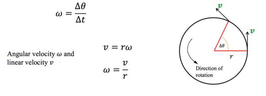
In physics, rotational motion (Fig 1) is the rotating motion of an object of any shape (regular or irregular) and any mass (uniformly or non-uniformly distributed or not distributed) which rotates around a center or an axis due to the rotational forces like torque.
It results in the formation of resultant forces like rotational kinematic energy, angular acceleration, angular frequency, angular velocity, angular momentum, speed, centrifugal force, centripetal force and moment of inertia.
Among the types of rotational motion, if we consider a body that is perfectly rigid (i.e., the body will not change or deforms its mass or shape) rotates around a fixed axis then such type of body comes under the rotational motion of rigid bodies.
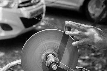
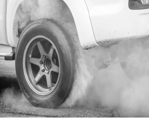
Let me ask you a question, consider rigid bodies like wheel stone (Fig 2) and car wheel (Fig 3) which has the same mass, same radius, and are spinning at the same rate than which one will move faster?
Obviously, the car wheel will only move faster. Comparatively both bodies will have different angular velocities since the uniform distribution of the car wheel’s higher mass lies at different radii when compared with wheel stone where the distribution of masses does not occur and remains constant.
Resulting in higher angular momentum and kinetic energy on the car wheel. For this reason, car wheels are employed with such a design so that higher mass particles are distributed at a far distance from the axis of rotation causing higher angular momentum and kinetic energy.
An increase in the distance of higher mass particles of a body from the center axis results in the formation of higher angular momentum and kinetic energy.
Now we have a question, at which distance, the body’s higher masses are uniformly distributed are concentrated towards the central axis, in the case of the car wheel.
Then we arrive at the radius (R) of the car wheel where the masses are uniformly distributed. The Radius R can be known as the Radius of gyration (R).
Radius Of Gyration (R):
Radius of gyration can be defined as the distance from the center axis at which the masses of all the elements of the body have to be placed so that the entire area is assumed to be concentrated, such that the moment of inertia about the axis is the same.
Radius of gyration is also known as the radius of rotation, which is the measure of how the mass of a rotating rigid body is distributed about its axis of rotation.
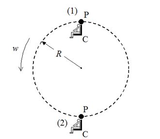
If you take a circular object, the radius (r) of that circular object need not be the same as the radius of gyration (R) of that same circular object. In case of the Ferris wheel (Fig 4), both the radius of the wheel (r) and radius of gyration (R) of the Ferris wheel are the same.It is due to the presence of masses that are uniformly distributed are located at the radius (r) of the Ferris wheel.
Hence, Radius of the Ferris wheel (r) = Radius of gyration of the Ferris wheel (R)
In simple terms, radius of gyration of a body about the axis of rotation is the radial distance to a point that would have a moment of inertia similar to the body’s actual weight distribution, if the total weight of the body were focussed on that point.
It is the perpendicular distance from point mass to the rotating axis.The unit of measurement of the radius of gyration is millimeter (mm). It’s S.I or Standard International system is meter (m). The radius of gyration is represented by the letter K.
Mathematically, radius of gyration of a body about a given axis is the root mean square distance of the various particles of the body from either its center of weight or a given axis, depending upon the correct usage.
The area moment of inertia is the product of the area of section and square of the distance.It is written as Area moment of inertia (I) = Area of section (A) x Square of Distance (r 2).
The radius of gyration with reference to the Area moment of inertia (I) and Area of section (A) is the square root of the area moment of inertia divided by the area of the section. It is further represented as R = √ I/A.
The moment of inertia can also be calculated as the product of the mass and radius of the gyration square. It is written as Moment of inertia (I) = Mass of the body (m) x Radius of gyration (K 2). It can also be written asK = √ I/m which is the formula for the radius of gyration where I represent the area moment of inertia and m represents the mass.
Scope of Radius of Gyration
Radius of gyration plays an important role in structural engineering. Radius of gyration helps us to know the ways in which the distribution of various segments of the item is present around an object. The practical use of radius of gyration as an area property is to estimate the maximum pressing load on a section before the section fails in buckling. Toothwheel uses this feature.
If you want to get the details of the moment of inertia of a body difficult to decipher in terms of the structure about a given axis, you should simply look up its radius of gyration and then knowing the weight apply the given formula to find the moment of inertia.
It helps to assess the solidness of a section It is used to detect buckling in a compression beam. The low value of the radius of gyration is used for structural calculations as this is the plane in which the member is most likely to buckle.
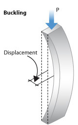
The diagram represents that under compression. There will be a bend in the thinnest plane. The radius of gyration can be used to find the inflexibility of a cross-section concerning its shape.
It plays an important role in selecting compression members like columns. The comparison of different structural shapes when they are subjected to compression loads along an axis can be made.
It is used to calculate buckling in a compression member. The radius of gyration values is used for structural engineering calculations. Square or circular shapes have a higher radius of gyration hence they are recommended for columns. They have the same value because the radius is the same throughout the process. Their radius does not change.
Case Studies – Radius Of Gyration For Different Shapes
1. Radius Of Gyration – Rectangle
Radius of gyration for rectangle shape can be calculated in the following ways based on the following cases,
- Case (i) Rectangle – with the line passing in the middle
Radius of gyration for a rectangle with the line passing in the middle is calculated as,
r = 0.289 h
where r represents the radius of gyration and h represents the height.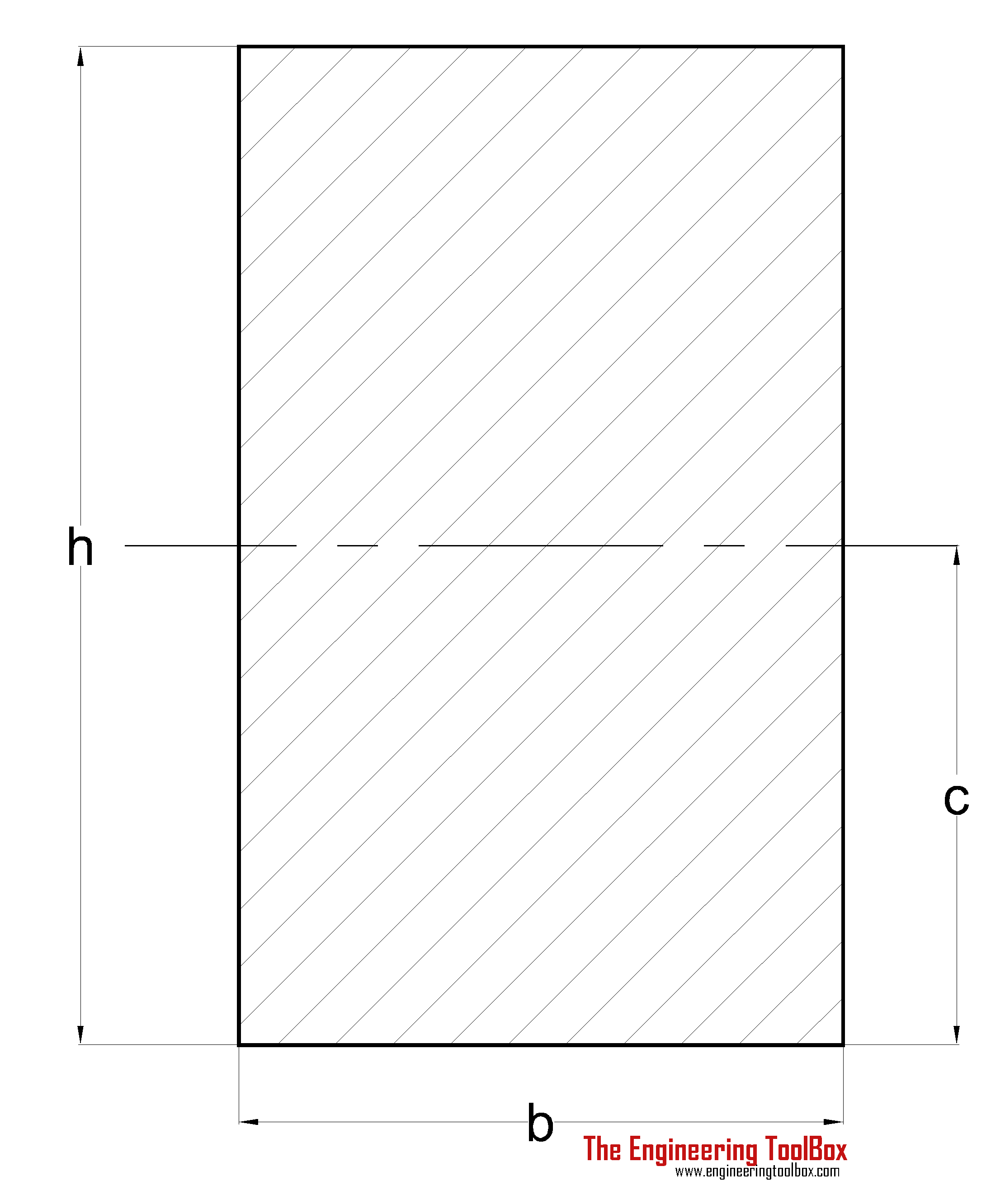
- Case (ii) Rectangle – with the central line not in the correct centre position
Radius of gyration for the rectangle with the central line not passing through the correct center position is calculated as,
r = 0.577 h
where r represents the radius of the gyration and h denotes the height.
- Case (iii) Rectangle – with the slanted line passing as the centre
Radius of Gyration for a rectangle with the slanting line is calculated as,
r = b h / √(6 (b2 + h2))
where r represents the radius, b represents the breadth, h represents the height, √ represents the square root.
- Case (iv) Rectangle – with the slanted line passing at the centre
Radius of Gyration for a rectangle with the slanted line passing as the centre is calculated as,
r = √(((h2 + cos2a) + (b2 sin2a)) / 12).
where r represents the radius, h represents the height, √ represents the square root.
2. Radius Of Gyration – Square
Radius of gyration for square shape can be calculated in the following ways based on the following cases,
- Case (i) Square – with no line passing in the middle
The radius of Gyration for square is calculated as,
r = √ ((H2 + h2) / 12)
where r is the radius, h represents the height, √ represents the square root.
- Case (ii) Square – with the slanted line passing at the centre
Radius of Gyration for an empty square with the line passing at the centre is calculated as,
r = √((H2 + h2) / 12)
Where r is the radius, h is the height and √ represents the square root.
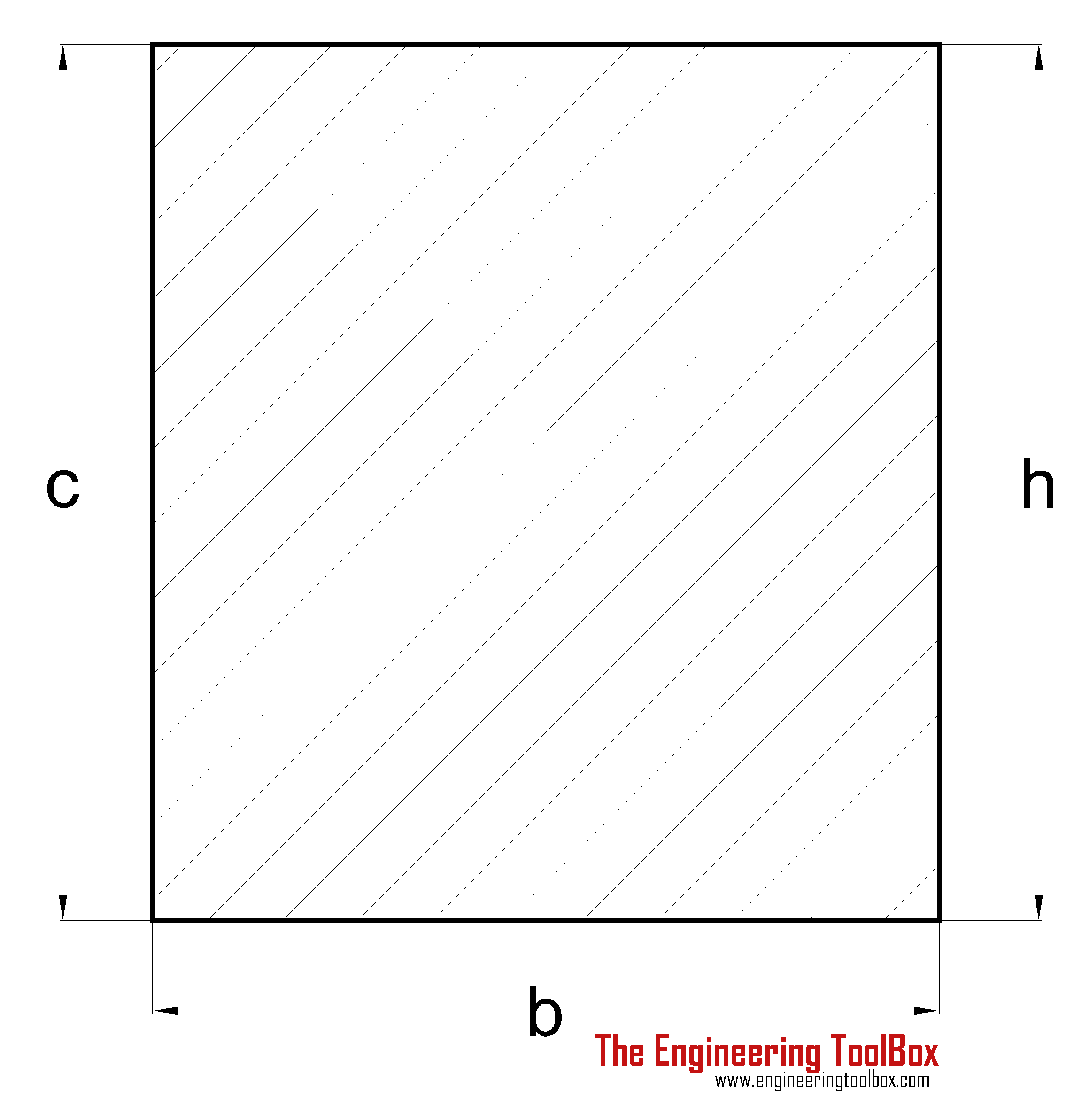
3. Equilateral Triangle with the centre position not in the true centre
- The radius of gyration for an equilateral triangle is calculated as
r = h / (18)1/2 where r represents the radius,h is the height and 1/2 represents the square root. It can also be calculated as r = h / (6)1/2
Radius Of Gyration Calculator
The radius of gyration can be calculated if a person knows the value for the inertia of the cross-section and area of the cross-section. The person has to follow the following steps:
- Type radius of gyrator on Google.
- Then open the page radius of the gyration page.
- Then enter the values of I and A which represents inertia and area. These boxes are positioned one below the other.
- Click on calculate and the answer is displayed on the third box.
- Click on reset to do calculations for the other values.
The other engineering calculators are present on the mechanical base website. The unit converter tool in this website is used to convert the units suitable for calculation. There are various websites available that also give calculators.
Radius Of Gyration Along the Axis
The x and y-axis consist of a line passing through them. The line is named r. The meeting line of x,y, and r is named dA. It is the area which these lines cross. The lines x,y,r, and dA are surrounded by the circle. The moment of inertia is calculated based on the particular axis.
The moment of inertia along the x-axis equals the integral of the product of the y axis square and dA which is the area of the meeting point. It is further presented as Ix= integral of (Y)2dA where Ix represents the moment of inertia at the x-axis.
The moment of inertia along the y axis equals the integral of the product of the x-axis square and dA which is the area of the meeting point. It is further represented as the Iy= integral of the (X)2dA where Iy represents the moment of inertia at the y axis.
The polar moment of inertia which is the moment of inertia in the z-axis is the sum of the inertia of the x and y-axis. It is represented as J=Ix+Iy where J represents the polar moment of inertia.
It is further represented as J=∫r2dA where r represents the line that runs between the x-axis and y-axis. The radius of gyration for the x,y, and the z-axis is represented by the symbols Ix, Iy, and Iz. It is represented as follows:
kx =(Iy/A)1/2.
ky=(Iz/A)1/2.
kz=(J/A)1/2.
where 1/2 represents the square root. J represents the polar inertia. Ix, Iy, Iz represents the moment of inertia. k represents the radius of gyration.
Also Read :
1.Functional Residual Capacity – What All You Need To Know?
2.Top 20 Best Restaurants With Outdoor Seating In New York
Thus the radius of gyration is very important in measuring the weight and volume of an object. It is used in the field of structural engineering to study the distribution of weight.
Leave a Comment